PIC16 Controlling LCD
PIC16 Controlling LCD
Here you will find the source code and schematics for interfacing LCD displays based on the Hitachi HD44780U controller with Microchip PIC16 microcontrollers using only 3 I/O pins.
The design utilizes a 74HC164 8-bit serial-to-parallel shift register to minimize I/O pin usage.
Required I/O pins:
- Clock - For shift register timing
- Data - For serial data transmission
- LCD Enable - For display control
The Clock and Data pins can be shared with other peripheral devices, making this solution ideal for pin-constrained applications.
The implementation is optimized for minimal assembly instructions to conserve program memory, particularly beneficial for microcontrollers with limited instruction space.
Schematics
 Controlling LCD with 74HC164 Schematics
Code
;******************************************************************************
; LCD interface for Microchip PIC16 microcontrollers.
;
; author: Ivan Dachev
; email: [email protected]
; web: www.lz2gl.com
; version: v1.0
;
;******************************************************************************
;
; Program control 8-Bit Serial-Input/Parallel-Output Shift Register
; 74HC164 which is connected to LCD.
;
; It is implement to use only 3 ports from microcontroller:
; CLOCK - clock for 74HC164
; DATA - data for 74HC164
; STROBE - enable/disable for LCD read operation
;
; 14.01.2007 Initial Version
; All source here is small parts from my programs
; so to be usable for own use, change position
; of file registers to fit your program.
;
;******************************************************************************
;******************************************************************************
; Bit flags for SYNSTATUS
;
; Constants _XXX_BITS are used to make bit swapping
; example:
; movlw _LOCK_BITS
; xorwf SYNSTATUS, F
;
#define _INSTLCD SYNSTATUS, 5 ;5-bit Instruction/Data flag for LCD
#define _INSTLCD_BITS B'00100000'
;******************************************************************************
;
; Main preferences for program.
;
#define OUT2LCD_DELAY_TIME .62
;Delay counter for OUT2LCD_DATA.
;Each iteration is 3 instructions we must wait about 37000ns
;so (20Mhz - number is 62) (10Mhz - number is 31)
;******************************************************************************
;
; Defines IN/OUT for PORTA
;
#define OUT_LCDCLOCK PORTA, 1 ;Share CLOCK at RA1 for LCD
#define OUT_LCDDATA PORTA, 2 ;Share DATA at RA2 for LCD
#define OUT_LCDSTROBE PORTA, 3 ;Strob signal at RA3 for LCD
;******************************************************************************
; Define commands for LCD
;
#define LCD_CLEAR B'00000001' ; Clear display, home cursor
#define LCD_HOME B'00000010' ; Send cursor home
#define LCD_8BIT B'00111100' ; 8-bit interface, 2 display lines, 5x10 font
#define LCD_DISABLE B'00001000' ; Disable entire display
#define LCD_ENABLE B'00001100' ; Display enable, no cursor
#define LCD_MODESET B'00000110' ; Increment cursor, no scrolling
#define LCD_CURSOFF B'00001100' ; Cursor off
#define LCD_CURSON B'00001111' ; Cursor on and blink at position
#define LCD_CURSRIGHT B'00010100' ; move cursor right one space
#define LCD_SETADDR B'10000000' ; Set display address for writing
;******************************************************************************
; File registers
;
;general temp
tmp equ 0x50
;general counter
count equ 0x53
;used for delay functions
delay1 equ 0x5D
delay2 equ 0x5E
;other variables
SYNSTATUS equ 0x73 ;boolean flags
;******************************************************************************
;
; INITLCD
; -------
;
; Initializing LCD
;
; 03.07.2004 Changed according to HITACHI specification !
;******************************************************************************
;
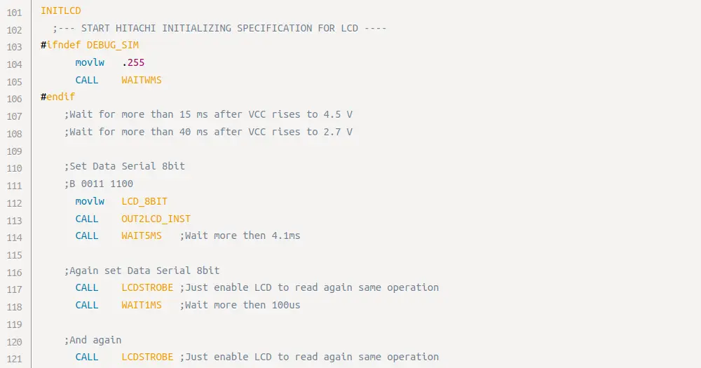
INITLCD
;--- START HITACHI INITIALIZING SPECIFICATION FOR LCD ----
#ifndef DEBUG_SIM
movlw .255
CALL WAITWMS
#endif
;Wait for more than 15 ms after VCC rises to 4.5 V
;Wait for more than 40 ms after VCC rises to 2.7 V
;Set Data Serial 8bit
;B 0011 1100
movlw LCD_8BIT
CALL OUT2LCD_INST
CALL WAIT5MS ;Wait more then 4.1ms
;Again set Data Serial 8bit
CALL LCDSTROBE ;Just enable LCD to read again same operation
CALL WAIT1MS ;Wait more then 100us
;And again
CALL LCDSTROBE ;Just enable LCD to read again same operation
;Set Data Serial 8bit, display 2 lines, Font to 5x10 dots
;B 0011 1100
movlw LCD_8BIT
CALL OUT2LCD_INST
;Turns display off / cursor off / blinck off
;B 0000 1000
movlw LCD_DISABLE
CALL OUT2LCD_INST
;Clears display and set address 0 of RAM
;B 0000 0001
movlw LCD_CLEAR
CALL OUT2LCD_INST
CALL WAIT2MS ;LCD_CLEAR need more wait to execute
;Set Cursor to move Increment / No shift
;B 0000 0110
movlw LCD_MODESET
CALL OUT2LCD_INST
;--- END HITACHI INITIALIZING SPECIFICATION FOR LCD ----
;Turns display on / cursor off / blinck off
;B 0000 1100
movlw LCD_ENABLE
GOTO OUT2LCD_INST
;RETURN goto will return ! same as return save place
;
; end ***********************************************************************
;
;******************************************************************************
;
; OUT2LCD_INST & OUT2LCD_DATA
; ---------------------------
;
; Output character or instruction in W to LCD
;
; For all OUT2LCD_DATA we must wait 37000ns
;
; For all OUT2LCD_INST expect below we must wait 37000ns
; for RETURN_TOHOME and CLEAR_DISPLAY we must wait 1,520,000ns
;
; Corrupts: count and tmp.
;******************************************************************************
;
OUT2LCD_INST
bsf _INSTLCD ;Change to instruction send
GOTO POUT2LCD
OUT2LCD_DATA
bcf _INSTLCD ;Change from instruction to data send
POUT2LCD
movwf tmp
movlw 008H
movwf count
NEXTOUT
bcf OUT_LCDCLOCK
GOTO $+1
bcf OUT_LCDDATA
rlf tmp,F
btfsc STATUS, C ;Check bit state skip if it is 0
bsf OUT_LCDDATA
GOTO $+1
bsf OUT_LCDCLOCK
decfsz count, F
GOTO NEXTOUT ;Go to send next bit
btfsc _INSTLCD ; OUT_LCDCLOCK is used for Instruction/Data switch
bcf OUT_LCDCLOCK
GOTO $+1
LCDSTROBE
;use this to repeat last operation again !
bsf OUT_LCDSTROBE ;enable LCD to read operation
GOTO $+1 ;wait LCD to do its job
bcf OUT_LCDSTROBE ;disable LCD to read operation
;--- from here LCD starts to execute operation ---
;--- so we need to wait it to finish him before next operation ---
movlw OUT2LCD_DELAY_TIME ;Wait for data and instructions
movwf delay1
decfsz delay1,F
GOTO $-1
RETURN
;
; end ***********************************************************************
;
;******************************************************************************
;
; Delay functions
;
; For 20Mhz
; 1 instruction - 200ns
; 1 call/goto instruction - 400ns
;
; For 10Mhz
; 1 instruction - 400ns
; 1 call/goto instruction - 800ns
;
; Here is formula to calculate each iterations call
;
; (767*(delay2-1) + 766)
; + 2 (call to WAITXXXLC)
; + 2 (init delay2)
; + 2 (goto delay2LOOP)
; + 2 final RETURN)
;
; 1ns = 10^-9s
; 1mcrs = 10^-6s
; 1ms = 10^-3s
;
; Names are for 20Mhz
;
; delay2 = 255 -> (iters 195592) (10Mhz 78,236,800ns) (20Mhz 39,118,400ns)
;
WAIT1MS
movlw .7 ;(iters 5376) (10Mhz 2,150,400ns) (20Mhz 1,075,200ns)
WAITWMS
movwf delay2
GOTO DELAY2LOOP
WAIT2MS
movlw .13 ;(iters 9978) (10Mhz 3,991,200ns) (20Mhz 1,995,600ns)
movwf delay2
GOTO DELAY2LOOP
WAIT5MS
movlw .33 ;(iters 25318) (10Mhz 10,127,200ns) (20Mhz 5,063,600ns)
movwf delay2
GOTO DELAY2LOOP
DELAY2LOOP ;(767*(delay2-1) + 766) iterations (without return)
#ifdef DEBUG_NODELAYS
RETURN ;USE ONLY FOR DEBUG
#endif
movlw .255
movwf delay1
DELAY1LOOP
decfsz delay1,F
GOTO DELAY1LOOP
decfsz delay2,F
GOTO DELAY2LOOP
RETURN
;
; end ***********************************************************************
;Datasheets
More Info
This post is licensed under CC BY 4.0 by the author.