V-Star Antenna
The V-Star antenna, designed according to Karl Rothammel’s specifications, is a high-performance multi-band system operating across 1-32MHz. This implementation demonstrates exceptional performance in both transmission and reception across the entire HF spectrum, making it particularly valuable for amateur radio applications.
Gallery
Description
The V-Star antenna, which is theoretically described in Karl Rothammel’s antenna manual, is the primary antenna used at our station. Through extensive experimentation, we found it to be highly effective and relatively simple to construct. However, implementation requires approximately 8 acres of land.
Our initial experiment with this antenna design began in 1992, using only three elements. We operated it for 4-5 years at approximately 200W power, achieving satisfactory results in both reception and transmission.
After dismantling it, we experimented with various antenna configurations, including a 3.5MHz pyramid, four 7MHz slopers, and various long-wire and dipole arrangements. Comparing the performance of these different antennas made us realize our mistake in dismantling the V-Star.
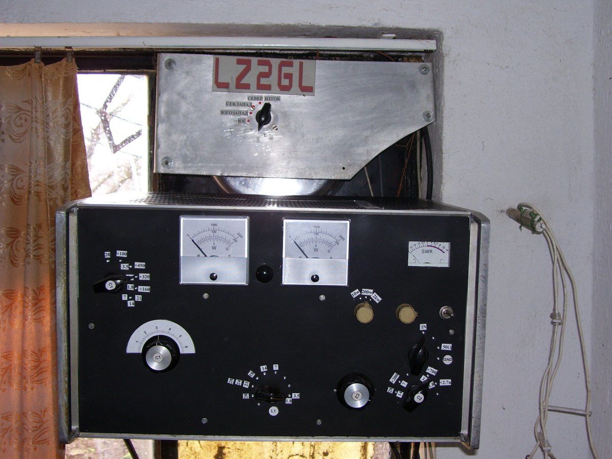
We decided to rebuild it, focusing not only on construction but also on optimizing the final tuning stage. While Rothammel’s book only described theoretical tuning using two Collins filters, we employed the MFJ 249 unit and initially used a small symmetric L-type antenna tuner. Following Rothammel’s specifications, we constructed the antenna with five 42-meter elements.
Initial testing revealed a high SWR in the 28MHz to 30MHz range. The antenna exhibited voltage tuning in the 28.000MHz region and current tuning in the 28.500MHz region. Despite experimenting with various symmetric T and L-type antenna tuners, we continued to encounter high SWR values.
Following DL7AB’s design modification, we installed Notch coils two meters from the feed point, using five turns of 2mm wire on a 50mm diameter form. The results were remarkable - the antenna achieved excellent tuning across 1.5MHz to 32MHz. We tested power levels ranging from 10W to 1kW, observing particularly impressive performance on 1.8MHz and 3.5MHz bands, with even better results at higher frequencies.
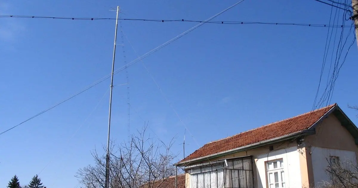
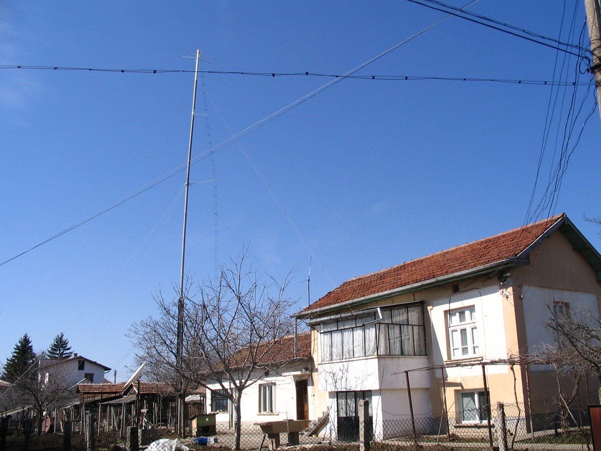
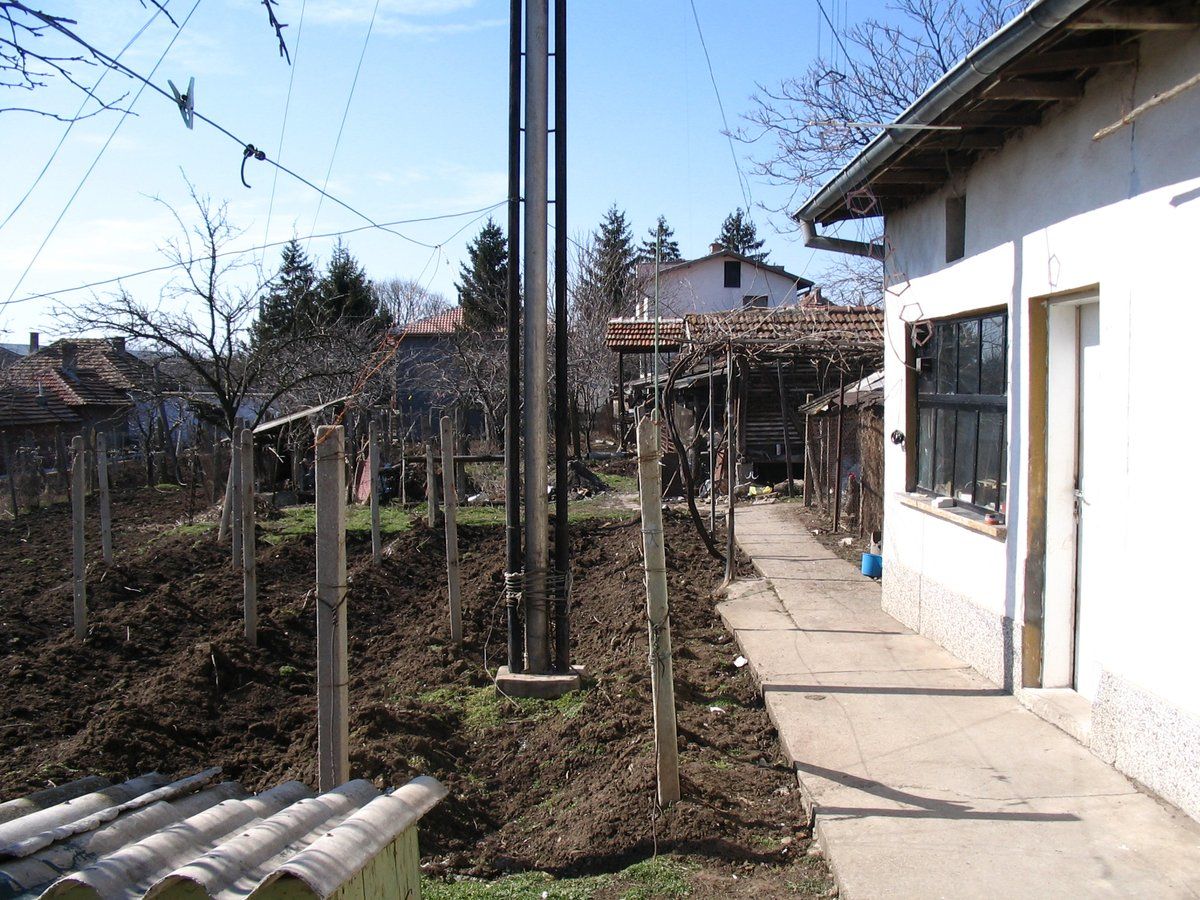
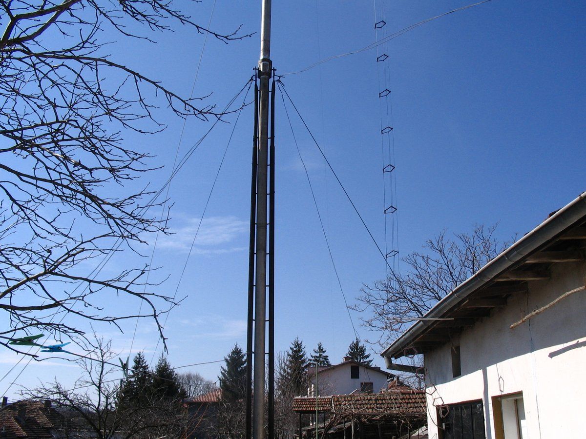
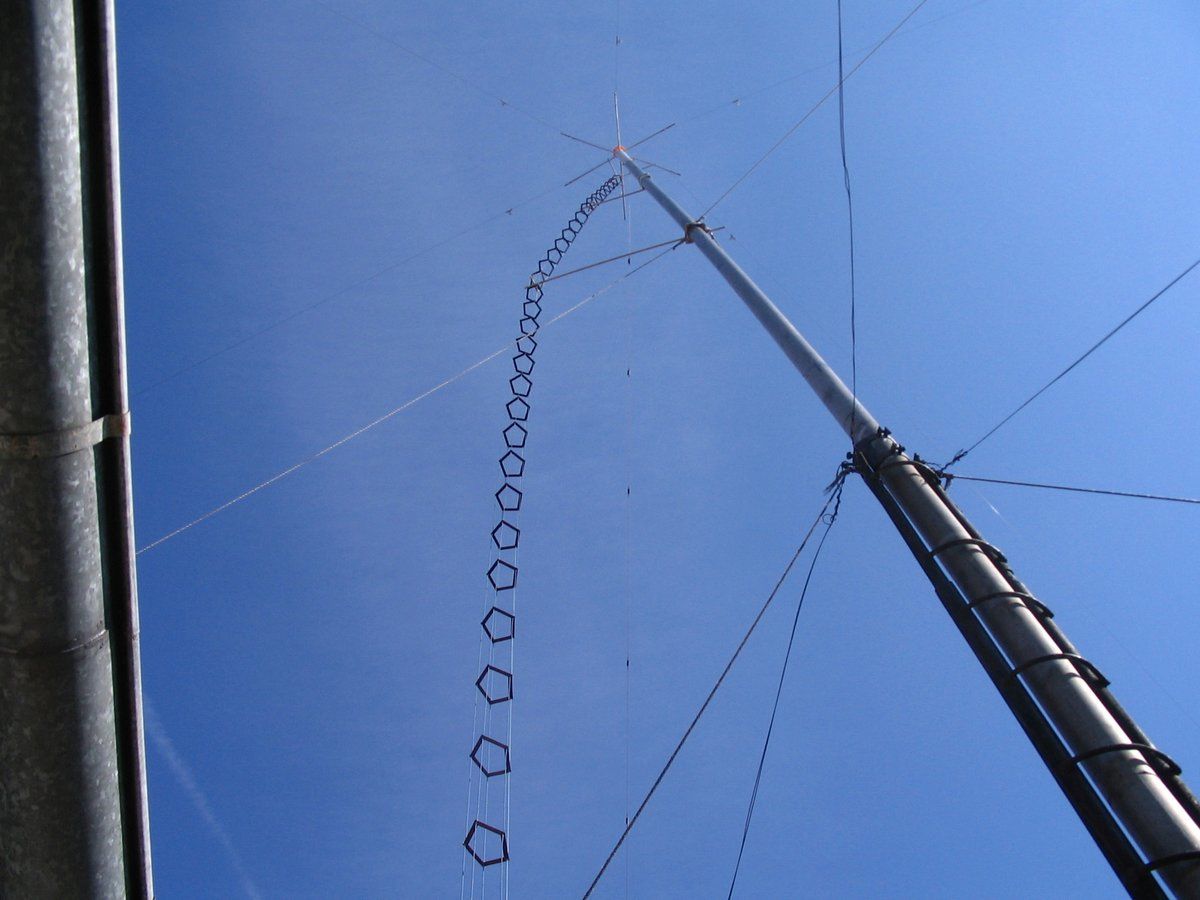
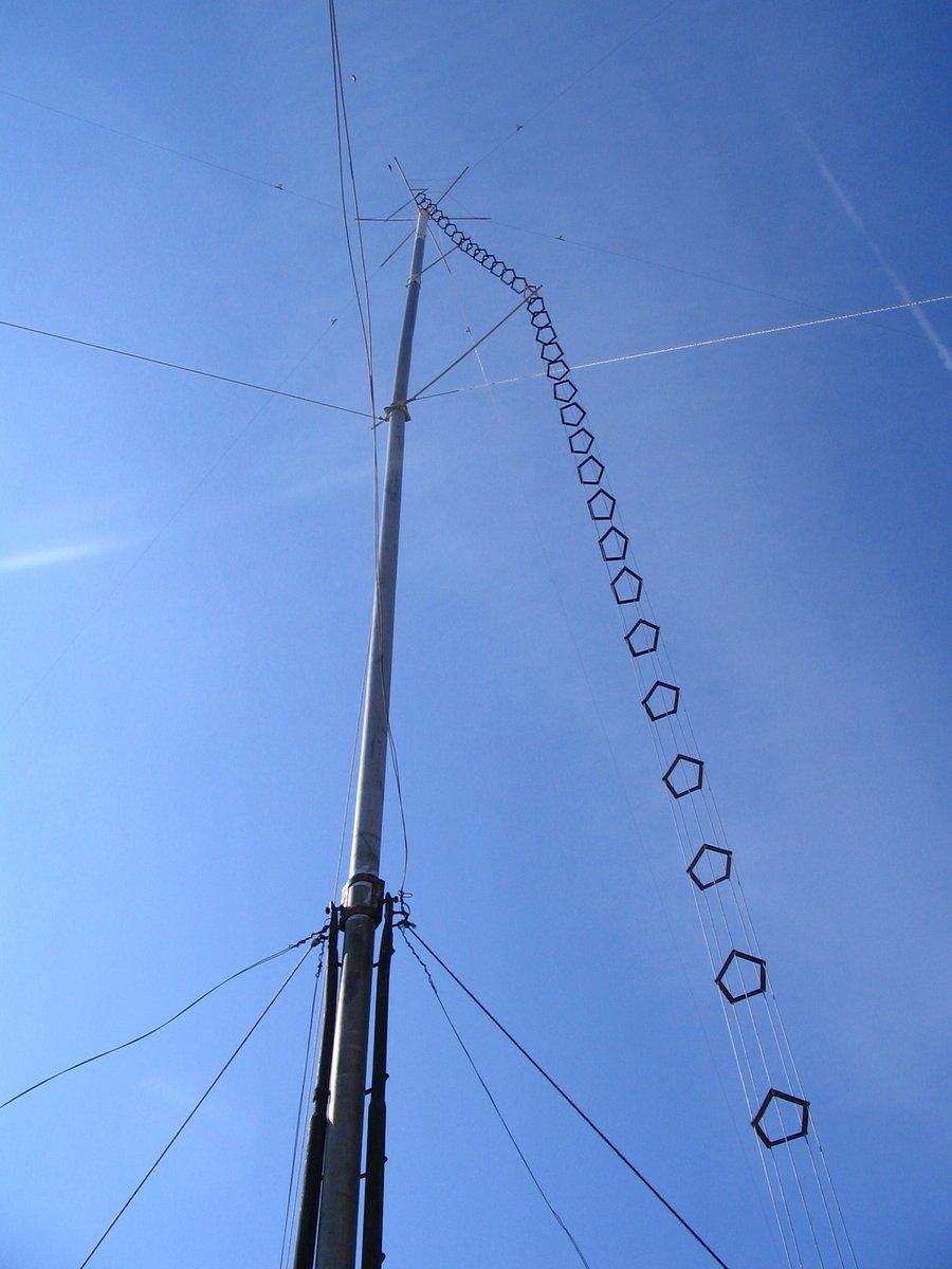
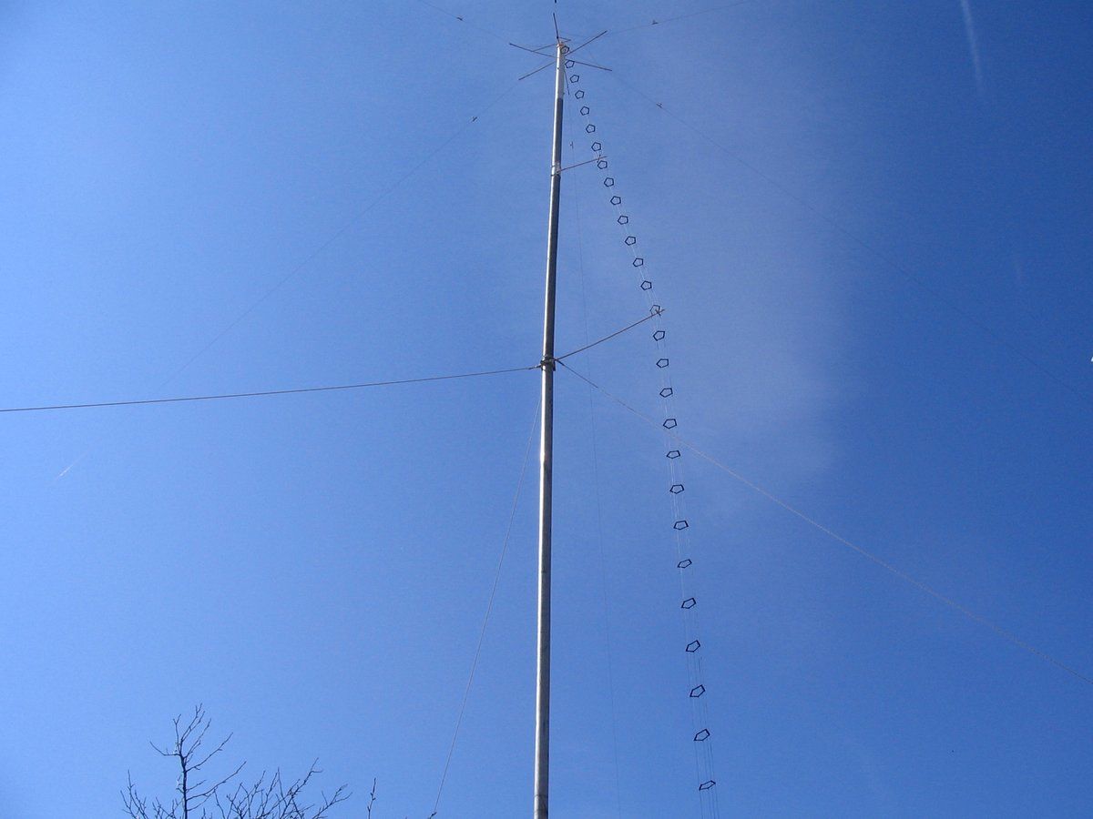
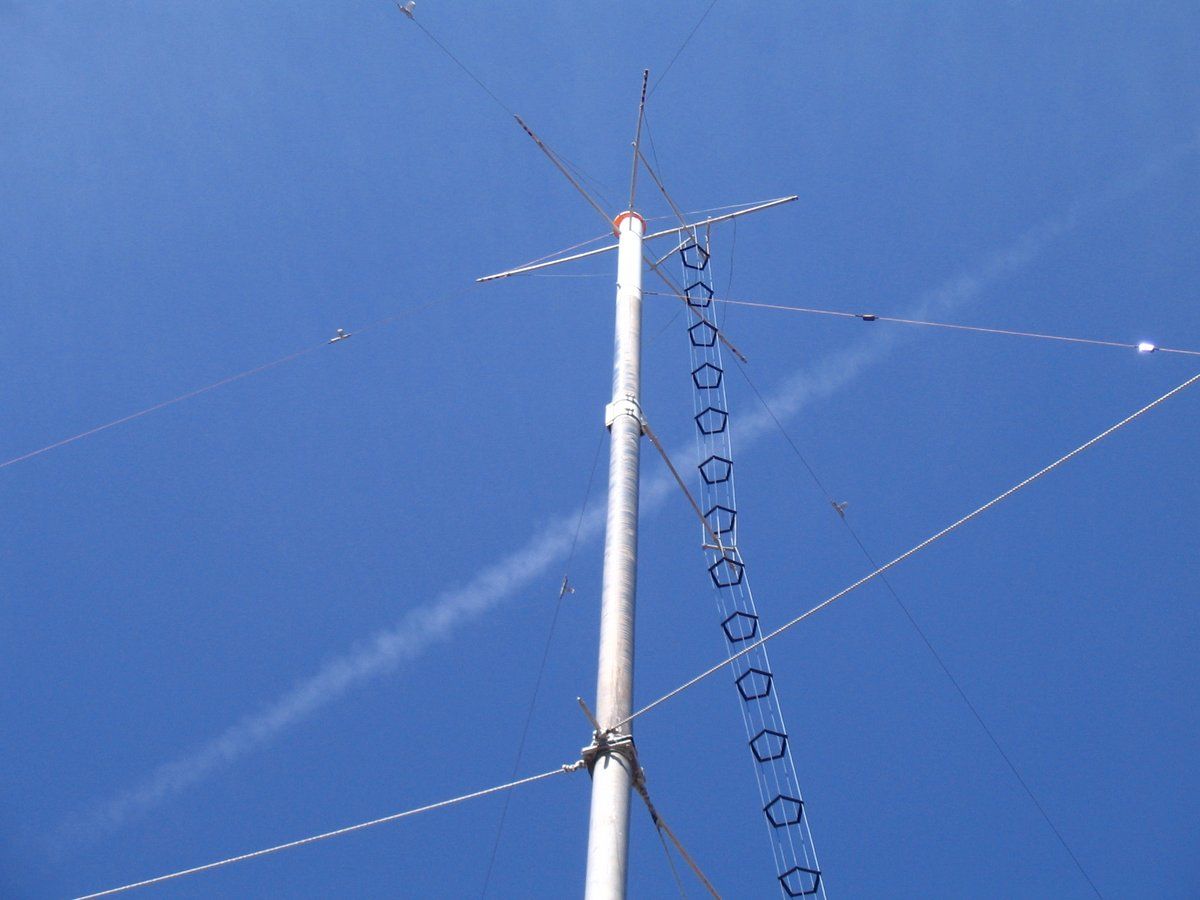
The central mast, constructed from 120mm diameter duraluminum pipes, stands at 21.5 meters in height. At its apex, five fiberglass bars are arranged in a star configuration, with a 4-meter diagonal span. Each rod extends 2 meters from the central pipe.
The antenna’s feed system consists of five balanced transmission lines, each 23 meters long, constructed from 2.5mm² stranded copper wire. The lines are separated by 100mm-long fiberglass spacers (1mm diameter), maintaining a 90mm spacing between conductors.